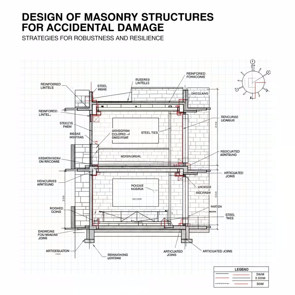
Masonry structures are traditionally designed to withstand normal load conditions, including dead loads, live loads, and environmental factors. However, unexpected accidental loads, such as explosions, vehicle impacts, and structural modifications, can pose serious threats to these structures. Designing masonry buildings to resist accidental damage is crucial for ensuring safety and minimizing risks associated with structural failures. This article explores various types of accidental loads, their risks, and design strategies to mitigate potential damage.

Types of Accidental Loads on Masonry Structures
Explosive Loads
Explosive loads can originate from both internal and external sources, such as bomb detonations, gas ignitions, or hazardous material explosions. Each type of explosion generates a unique pressure-time curve. Despite their dynamic nature, explosive loads are typically considered as static forces in design evaluations.
Impact Loads
Impact loads occur due to collisions with masonry structures, such as vehicle crashes into walls or construction equipment accidents. These loads are sudden and localized, requiring reinforced masonry designs to prevent structural failure.
Other Loads
Additional accidental loads include foundation settlement, modifications to the building structure, and extreme weather events. These factors may contribute to unforeseen structural stress and failure.
Risk of Occurrence of Accidental Loads
The probability of accidental loads occurring varies based on factors like geographical location and structural usage. While some risks, like lightning strikes, are generally considered acceptable, others, such as explosions, require stringent safety measures. Cost-benefit analysis is essential to balance structural safety and financial feasibility.
Statistical Analysis of Accidental Risks
A comparative analysis of accidental deaths highlights the importance of addressing these risks. Table-1 presents statistical data on accidental deaths per annum in the United States:
| Cause | Risk per Person per Year |
|---|---|
| Motor vehicle | 2.7 x 10^-4 |
| Falling | 1.0 x 10^-4 |
| Fire | 4.0 x 10^-4 |
| Drowning | 2.8 x 10^-4 |
| Firearms | 1.3 x 10^-4 |
| Poisoning | 1.1 x 10^-4 |
| Earthquake | 8.0 x 10^-4 |
| Lightning | 5.5 x 10^-4 |
These statistics emphasize the need for integrating safety measures against accidental damage in masonry structures.
Likelihood of Progressive Collapse in Masonry Structures
Progressive collapse occurs when an initial local failure leads to the disproportionate failure of an entire structure.
Types of Load-Bearing Masonry Constructions
- Type A: Structures with an external wall without returns or only one internal return. The remaining section suspends on the slab above when a panel is removed.
- Type B: Internal walls without returns where floor slabs provide support.
- Type C: Structures experiencing high local stress due to section removal, causing reliance on return walls.
Historical examples, such as the Ronan Point collapse, demonstrate the importance of progressive collapse prevention.
Methods of Masonry Structure Design for Accidental Damage
Design Against Accidental Damage Occurrence
Preventive strategies, such as limiting gas usage in buildings, can reduce the likelihood of specific accidents. However, this method does not guarantee complete elimination of progressive collapse risks.
Design Against Progressive Collapse
This approach focuses on ensuring stability even when local failures occur. The three primary methods include:
- Three-dimensional analysis of the entire structure.
- Two-dimensional sectional analysis to evaluate load distribution.
- Storey-by-storey approach, which assesses stability after the removal of a load-bearing element at a specific level.
Design Recommendations for Masonry Structures (BS 5628 Guidelines)
BS 5628 provides guidance on mitigating accidental damage through reinforcement strategies, particularly through tie systems.
Use of Ties in Masonry Structures
BS 5628 mandates the use of ties for structures above four storeys, ensuring integrity and load redistribution.
Vertical Ties
Vertical ties extend from the foundation to the roof and must be anchored securely. The force required for these ties is calculated using:
Fv=max(Ah,t)
where:
- A = horizontal cross-sectional area of the wall or column.
- h = clear height of the structure.
- t = thickness of the masonry component.
Horizontal Ties
Horizontal ties ensure lateral stability and are classified into:
- Peripheral ties – Installed within 1.2m of the building’s edge.
- Internal ties – Spanning across the structure to connect load-bearing elements.
- External wall ties – Preventing detachment of exterior walls.
- External column ties – Reinforcing columns against lateral forces.
The force required for horizontal ties is determined by:
Fh=min(Ns,5h)
where Ns is the number of storeys, and h is the storey height.
Conclusion
Accidental damage in masonry structures poses a significant threat, requiring comprehensive design strategies for risk mitigation. By understanding various accidental loads, assessing risk probabilities, and implementing reinforcement techniques such as vertical and horizontal ties, engineers can enhance structural resilience. Future advancements in materials and construction methods will further improve the safety of masonry structures against unforeseen loads.
