
In structural design, safety is paramount. Engineers must ensure that the materials, loads, and forces involved in a structure’s design are carefully balanced to prevent failure. Various safety factors and design methods exist to achieve this balance, with one of the most commonly used being the Load and Resistance Factor Design (LRFD) format. Adopted by the American Concrete Institute (ACI) Code, LRFD provides a reliable and systematic approach to ensure that structures are both safe and efficient. This article explains the LRFD format, its underlying principles, and how it compares to other design methods.
Introduction to LRFD Format
The Load and Resistance Factor Design (LRFD) format is a widely accepted design methodology in structural engineering, particularly in the design of reinforced concrete structures. The ACI Code incorporates LRFD as a means of addressing safety in structural design by considering both the loads and the resistance (strength) of materials.
The core idea behind LRFD is that both the loads applied to a structure and the resistance of the materials used to build that structure are subject to uncertainties. To account for these uncertainties, LRFD applies a set of factors to both the load and resistance components of the design. These factors help ensure that a structure is designed safely, considering the variability in material properties, dimensions, and the possibility of unexpected overloading.
Concept of LRFD in Classical Reliability Model
To understand how LRFD works, it’s useful to look at the classical reliability model. In this model, safety is achieved when the structure’s resistance to load is greater than or equal to the load effects. Mathematically, this can be expressed as: ![]()
Where:
- Rn is the nominal or characteristic value of the resistance (material strength or structural capacity).
- Sn is the nominal or characteristic value of the load effect (the forces acting on the structure).
- φ (phi) is the resistance factor.
- γ (gamma) is the load factor.
The equation reflects the basic safety principle that the applied load should never exceed the resistance of the material or structure.
Role of the Resistance Factor (φ)
In the LRFD format, the resistance factor (φ) accounts for uncertainties related to the strength and properties of the materials used in construction, as well as the assumptions made during design calculations. These uncertainties might arise from variations in material quality, inaccuracies in manufacturing or construction, and imperfections in theoretical models used to calculate resistance.
The resistance factor is typically less than unity (i.e., φ < 1), meaning that engineers intentionally reduce the calculated resistance to account for these uncertainties. By applying this reduction, the design is more conservative and ensures that the structure has a greater likelihood of withstanding loads without failure.
For example, if a material’s theoretical strength is calculated to be 500 MPa, applying a resistance factor of 0.9 would result in a design resistance of 450 MPa. This accounts for potential weaknesses in the material or construction process that might reduce its actual strength.
Role of the Load Factor (γ)
Conversely, the load factor (γ) accounts for the uncertainties associated with the loads that a structure may experience. These uncertainties can include variations in the magnitude of the loads, such as fluctuations in live loads (e.g., traffic or occupancy), unexpected environmental forces (e.g., wind or seismic activity), or inaccuracies in estimating the load effects.
The load factor is typically greater than unity (i.e., γ > 1), reflecting the possibility of overload or more extreme conditions than initially assumed in the design. By applying a load factor greater than one, the design takes into account the potential for higher-than-expected load effects, providing an additional margin of safety.
For example, if a load effect is calculated to be 100 kN, applying a load factor of 1.6 would result in a design load of 160 kN, effectively ensuring that the structure can withstand higher-than-expected loads.
Safety Condition
The LRFD safety condition ensures that a structure will remain stable and functional under the applied loads. The equation:
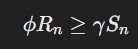
must be satisfied to meet safety requirements. This equation expresses the balance between the “reduced” resistance (due to the resistance factor) and the “amplified” load (due to the load factor). By applying these factors, LRFD ensures that the structure has an adequate safety margin, accounting for both material weaknesses and potential load surpluses.
In practice, this equation means that the reduced resistance, represented by φ Rn, must always be greater than or equal to the amplified load, represented by γ Sn. If this condition is met, the design is considered safe.
Rearrangement of Safety Condition (WSM and ULM Concepts)
To further understand the safety philosophy in LRFD, we can look at how the safety condition is related to two other traditional design methods: the Working Stress Method (WSM) and the Ultimate Load Method (ULM).
- WSM (Working Stress Method): In WSM, the focus is on the material’s working stress (or allowable stress), which is derived from the nominal resistance divided by a factor of safety (FS). The equation is often written as:
 .In this case, the factor of safety (FS) is applied to the material strength to ensure that the material is not overstressed during normal use. The safety margin is built into the strength of the material.
 - ULM (Ultimate Load Method): In ULM, the focus is on the ultimate load the structure can support before failure. The load factor (γ) is applied to the loads to ensure that the structure can handle extreme conditions. The equation in ULM would look like:
 Here, the load factor ensures that the structure can handle more than the expected load before failure occurs.
 .In this case, the factor of safety (FS) is applied to the material strength to ensure that the material is not overstressed during normal use. The safety margin is built into the strength of the material.
Conclusion
In conclusion, the Load and Resistance Factor Design (LRFD) format provides a systematic and reliable approach to ensuring safety in structural design. By applying both resistance factors (φ) and load factors (γ), LRFD accounts for the inherent uncertainties in material strength and load effects, providing a margin of safety that helps prevent failure.