
Reinforced Concrete (RC) walls are structural elements that combine concrete and reinforcement steel to withstand loads efficiently. These walls are widely used in buildings where heavy slab loads need support or where masonry thickness is restricted. RC walls offer strength, durability, and stability in various applications, including high-rise buildings, industrial structures, and retaining walls.
Classification of Reinforced Concrete Walls
A. Plain Concrete Wall
- Contains reinforcement less than 0.4% of the cross-sectional area.
- Designed primarily for compression loads with minimal tensile stresses.
- Typically used in non-load-bearing applications or low-rise structures.
B. Reinforced Concrete Wall
- Contains reinforcement exceeding 0.4% of the cross-sectional area.
- Design follows principles similar to RC columns, considering axial and bending effects.
- Used for structural walls in buildings, shear walls, and earthquake-resistant structures.
III. Load Transfer and Design Approach
RC walls primarily transfer axial loads from slabs and beams to the foundation. The design considers:
- Axially Loaded Walls – Walls subjected to direct vertical loads with negligible bending.
- Axially Loaded Walls with Uniaxial Bending – Walls experiencing additional bending moments due to eccentric loads or lateral forces.
IV. Slenderness Ratio and Wall Classification
The slenderness ratio helps classify walls as short or slender:
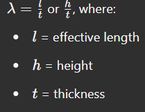
- Slenderness Ratio Formula:
or , where:

- Classification:
- Short Wall: Slenderness ratio <=12io
- Slender Wall: Slenderness ratio >12
V. Braced vs. Unbraced Concrete Walls
A. Braced Walls
- Supported laterally by cross walls or rigid frames.
- Designed primarily for axial loads with minimal moment considerations.
B. Unbraced Walls
- Lacks lateral support and must resist additional moments from deflections.
- Moment calculations include minimum eccentricity effects.
C. Special Cases
- Cantilever Walls: Supported at one end, common in retaining structures.
- Shear Walls: Resist lateral loads from wind or earthquakes.
VI. Design Guidelines for Reinforced Concrete Walls
A. Slenderness Limits
- Braced Walls: Slenderness ratio
- Unbraced Walls: Slenderness ratio
B. Short Braced Wall Design
- Axial load capacity formula:
C. Short Unbraced Wall Design
- Minimum eccentricity:
- Moment calculation:
D. Slender Braced Wall Design
- Additional moment considerations per SP16 Table 1.
E. Slender Unbraced Wall Design
- Similar to slender braced walls but includes greater moment effects.
VII. Detailing of Reinforcement (IS 456 Guidelines)
A. Plain Concrete Wall Reinforcement
- Minimum vertical reinforcement:
- HYSD steel: 0.12%
- Mild steel: 0.15%
- No transverse reinforcement required.
B. Reinforced Concrete Wall Reinforcement
- Minimum vertical reinforcement: 0.4%.
- Maximum spacing: 450mm or 3t (whichever is lesser).
- Minimum thickness: 100mm.
- Walls thicker than 200mm require double grid reinforcement.
VIII. Support Conditions for Effective Length (BS 8110 Reference)
- Both ends fixed – Maximum restraint, shortest effective length.
- Both ends hinged – Moderate restraint, used in practical designs.
- One end fixed, one end free – Longest effective length, applicable in cantilever walls.
- One end fixed, one end hinged – Intermediate effective length.
Conclusion
RC walls play a crucial role in structural stability, especially in high-rise and seismic-resistant designs. Proper classification, load considerations, and reinforcement detailing per IS 456 and BS 8110 ensure safety and efficiency. Understanding the slenderness ratio, bracing conditions, and support types helps in optimizing wall performance and durability.